Southern Pacific Lines
Coast Line Division
“The Route of the Octopus”
Southern Pacific Lines
Coast Line Division
“The Route of the Octopus”
Track Items
Bumping Posts
Buda
SP used Buda No. 30 steel bumping posts, at least some times. These have good-sized channel in the compression members and rod for the tension legs.
Reference
They are illustrated in the 1942 Railway Engineering and Maintenance Cyclopedia and the 8th edition (1955) Railway Track and Structures Cyclopedia, and probably in other cyclopedias, too.
Modeling Bumping Posts
Walther's
You can modify some commercially available (Walther's) HO bumping posts to pretty well match the Buda No. 30.
Hayes (Western-Cullen-Hayes)
http://www.wch.com/pdf/catalog/bpfacts.pdf
The two house tracks they used to have at the Sacramento depot had what looked to me like Hayes. They also had metal steps up the back for access to a PV that often were parked there.
Jim Elliot
Derail Stands
The SP adopted these types of signs in 1908 and they originally were supposed to be used at locations where there were no high switchstands indicating a derail. However, in California, the Derailing Switch Law, Act 6482 stipulated that such signs be used at all derail locations regardless if there was a high derail switchstand or not.
They were just like a regular high switch stands except they had a little metal plate below the target that read "DERAIL".
Prior to 1956wood post 4” square, 4’ high
Post 1956metal post
Dimensions of the sign plate and the lettering would remain the same.
Placement
Derail stands are placed on the same side of the track as the desired derailing direction.
Derail Sign
Derail switch. stand where supposed to have a Derail sign attached to the stand or on a post within 4 ft of switch.stand. Today the signs are purple in color with a white "D".
Paint
Derail targets during SP times were painted red. The front of the post is painted white.
Lettering & Numbering
The metal plate below the target read "DERAIL". or "Derail Switch" on them. Later the word "Switch" had mostly been eliminated on derail switchstand targets.
John Sweetser
Repro of a 1908 SP derail sign plan. Nov. 1972 NMRA Bulletin, pg. 37
1956 revision Southern Pacific Lines Common Standard Plans, Vol. 1, pg. 28
References
See Page 55 of Signor's Beaumont Hill book has a 1924 photo taken at Calipatria in the Imperial Valley that shows two wooden derail signs next to two derails.
The best photo showing a wooden derail sign, can be found on pg. 197 of Austin & Dill's "The Southern Pacific in Oregon."
John Sweetser
In the photos section, there’s two pictures of derails which protect the SP mainline at the Granite Rock Quarry at Logan taken in 2001. http://finance.ph.groups.yahoo.com/group/Espee/photos/browse/9684?m=l
Hot Box / Dragging Equipment Detectors
LA and SJ Div Special Instructions dated Jan. 1, 1969 list several locations for Hot Box Detectors under Rule 705. Since they are listed as being equipped with illuminated H or W letters displayed on regular block signals (on Santa Barbara Sub Div as example), the readout must have been inside a bungalow, and not the "scoreboard" style lite display.
Pat Flynn
The "scoreboard" style readout screens began showing up about 1973.
Wesley Fox
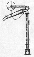
Oil Column
"Rose" oil column
Reference
CS Plans, Vol 5. pg. 49
Trainline #117, pg. 43
Modeling Oil Column
Century Foundry Models
The oil column seems to match photos well.
Tony Thompson
Telltales
The Espee policy on telltales only references to them in the SP "Rules and Regulations for the Maintenance of Way and Structures" (1953) is that they be kept in good repair. There is some discussion of them (under "Bridge Warnings") in the 1926 "Railway Engineering and Maintenance Cyclopedia," which states that they were to be located from 100 to 300 feet away from bridges on main tracks, and closer distance on side tracks where train speed was presumed to be slower. The same would apply to tunnels.
If two tunnels were fairly close to each other, the usual practice seems to have called for one telltale midway between them in addition to telltales at their outer approaches. For example, tunnels 3 and 4 in the Tehachapis were a little over 300 feet apart and had a telltale at the approximate midpoint between them. See the photo in the upper right on page 4 of the October 1952 issue of "The Western Railroader" (the same photo can be found in the USGS publication "Earthquakes in Kern County California During 1952."
Tehachapi tunnels 5 and 6 were further apart, about 600 feet, and each of these two tunnels apparently had its own full pair of telltales (Tunnel 6's west telltale can be seen in the photo on the lower right on pg. 4 of the Oct. ' 52 Western Railroader and also in the video "Tehachapi Loop" produced by Video Rails).
By the way, the word "telltales" has been spelled correctly in the title of this thread. Any other version is incorrect.
John Sweetser
SP Water Columns
There were two types of SP Water Columns, wheel and standpipe. Based on photos, the wheel-actuated water columns on the SP were much more numerous than the lever-actuated ones were. In some locations, such as San Luis Obispo and Santa Barbara, they used the lever-actuated type.
There’s no "Typical" flow rate (in gallons per minute) of a "typical" SP water (recognizing that there were different manufacturers that produced these for the system, and that municipalities provided differing water pressure). Looking at a ballpark answer, it is like 1000 gallons per minute or more.
Tenders were refilled on mountain grades in times ranging from ten to twenty minutes, but of course tenders were not necessarily very close to empty.
Tony Thompson
Wheel Activated
Known as the Fairbanks-Morse “Wheel Activated” Water Column, it was the SP preferred design. The SP used them but did not design them. Columns of this kind were used by other railroads throughout the U.S too.
Photos date back to the late 1920s of wheel-actuated Fairbanks-Morse water columns.
The "wheel actuated" column of Tehachapi water columns are here:
The large wheel (about 3 feet in diameter) was used to control the water flow. The SP ones were 16 feet tall.
Larry Castle
A 1928 SP photo of a wheel-actuated Fairbanks-Morse/Sheffield water column can be found on pg. 28 of "Southern Pacific Lines Common Standard Plans, Vol. 5" while 1928 photos of the same type on the Wheeling & Lake Erie can be found on pg. 25 and pg. 27 of the August 1986 issue of Mainline Modeler.
Rigid Column (Standpipe)
The "Sheffield/FM" 12A water column (standpipe) operates with a lever, instead of a wheel.
Tim O'Connor
An even earlier Fairbanks-Morse/Sheffield water column design is on pg. 34 of "Southern Pacific Lines Common Standard Plans, Vol. 2." is also found on pg. 128 of John Signor's Shasta Division book. The water column in the photo can't be more than a year old. The water column in the photo is very, very similar to a drawing labeled "Sheffield Water Crane" found on pg. 25 of the Aug. ' 86 Mainline Modeler. This leads me to believe that the wheel-actuated water columns weren't around in 1910.
John Sweetser
There’s a Santa Fe standard plan for a lever-actuated "Fairbanks, Morse & Co. Sheffield No. 12-A" water column that is dated December 1937. The Fairbanks-Morse's/Sheffield's lever-actuated column superseded the wheel-actuated column in the company's product line and that this happened in 1937.
Another style was the Poage Style "H" Water Column with Fenner Spout. These were in 16-foot heights.
Reference
See: http://www.atsfrr.com/resources/Sandifer/Emporia/Engine%20Service/Engine.htm
http://www.theproto87chronicles.com/water_column/water_column.html
See both at middle of the page. http://model-railroad-hobbyist.com/node/2728
Southern Pacific Passenger Cars, Vol 5: Lounge, Dome & Parlor, pg. 71
Modeling Water Columns
There are excellent models matching some of the types SP used in many places. But be sure it will clear tall tenders. Sometimes these detail parts are for non-SP railroad practice. Some importers have brought in water columns only 13 or 14 (scale) feet high. Clearing an SP tender deck usually needed at least 15 ft.
Tony Thompson
Modeling Wheel Water Columns
Diamond Scale (Fairbanks-Morse)
The Diamond Scale water and oil columns are based on SP designs.
Spen Kellogg
Diamond Scale's water and oil columns can be seen at:
John Sweetser
A photo on pg. 31 of the First Quarter 1990 issue of Santa Fe Modeler identifies a water column similar to Diamond Scale's model.
Modeling Rigid Standpipe Water Columns
Overland Models (Poage)
This type was commonly used on the SP, but OM supplied them in a short height which might be suitable for eastern roads’ tenders but certainly would not clear the much larger tenders common on western railroads. They later brought in an additional run of Poage columns with 16-foot heights. Perfect!
Tony Thompson
Tichy (Fairbanks-Morse)
Tichy makes an F-M water column (standpipe) that operates with a lever, instead of a wheel.
Tim O'Connor
Miscellaneous Support Equipment
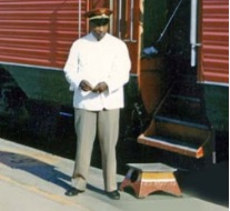
SP Boarding Step
There is a step stool used for boarding passenger cars when there is not a raised platform. It is generally called a "step box" or a “boarding step". Railroadiana collectors tend to call it a "step stool", smaller ones are sometimes called "Conductor's Step Stool".
Three types were sold: sheet metal steps made by "Morton Co." with a metal label attached, cheap Mexican copies (MUCH HEAVIER), and cast aluminum "Pullman" step stools.
On the 1937 Pullman order it stated that "Step Boxes were not required" so it appears unlikely that any step boxes were delivered with the train.
Ken Clark
Paint
One in a museum collection was painted "Aluminum" (a silver color, but NOT silver). It was the most common color. Some came painted in Daylight colors, but these were generally painted for use with the Coast Daylight when it was first placed in service. The lettering was not highlighted in any way and it was painted the same color inside and out.
Pat LaTorres
The Morton SPCo step is painted SP dark olive (a two tone paint scheme) which matched the heavyweight cars. The tread was painted aluminum. In later years when the silver/red scheme for passenger cars was adopted, some of the steps would likely have been repainted. To fully restore the step it may need new rubber feet, they are always on sale on eBay although the price seems almost double from a few years ago.
Kenneth R. Clark
In Wright's book, on page 632 there is a crew picture with four Daylight step boxes in the foreground. Although Black and white, the step boxes appear to be multicolor, perhaps Daylight red top and bottom with a Daylight Orange band in the middle. They appear to be standard Morton Steps with the Daylight Herald (monogram in Wright's book) on the side that does not have a cutout.
Ken Clark
Lettering & Numbering
The step has SP Co. standard lettering stamped on the stool side.
David Bond
The step boxes in the photos in Wright's book do not appear to have the embossed (raised) SP Co. that is on my SP Green Morton Step stool. That would make it likely that the step stools pictured were stock items (w/o RR markings) that were painted with the Daylight Herald in the SP shops.
Ken Clark
Modeling SP Boarding Step
Modeling Paint
Go to Home Depot and in the Glidden section of color cards you will find GLN43 which is labeled Dark Olive. I have used it on full sized items and the color is real close.
Jim Elliot
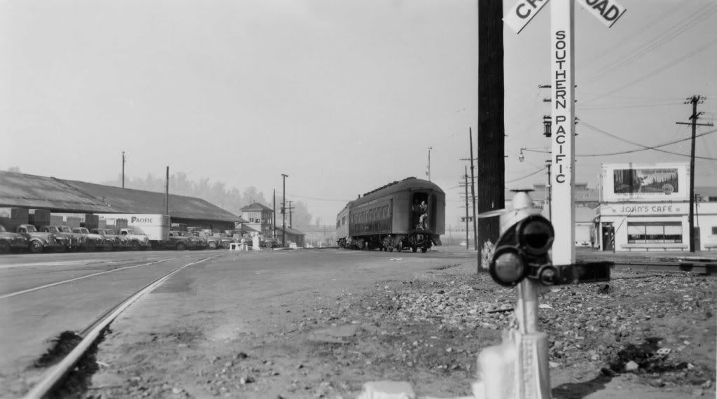
SP Crossbucks Posts
Lettering & Numbering
SP Crossbucks posts had the lettering "Southern Pacific"from below the crossbuck vertically down the post. They were pretty common. There is such a post in Bakersfield and Exeter, CA.
Here are a couple of photos. http://i158.photobucket.com/albums/t116/railsnw/signal-01.jpg
http://www.geocities.com/jim_lancaster.geo/spphotos/spcrossbuck.jpg
Note that SOUTHERN PACIFIC is in a sort of "ghost" lettering.
http://www.geocities.com/jim_lancaster.geo/sp_photos/sjvrr_crossbuck.jpg
Jim Lancaster
In Armona, California, cross bucks looked like the photo in Exeter except instead of it reading Southern Pacific on the vertical post it read: WATCH FOR THE CARS
"LOOK OUT FOR THE CARS” was the standard phrasing at one time on some SP crossbucks posts.
Modeling SP Crossbucks Posts
Lettering & Numbering
Decals
Microscale
Both the HO and N scale decal sets have the vertical "SOUTHERN PACIFIC" as seen on crossbuck posts.
87-1376 for HO, 60-1376 for N. "Southern Pacific Station Signs, Signal Milepost Numbers,
Etc (2 Sheets)
Unlike normal decal sets from Microscale, this set consists of TWO decal sheets due to the large number of station locations and other data in this set.
Harry K. Wong
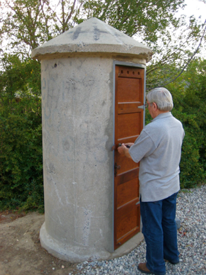
SP Concrete Phone Booths (CS 1810)
Placement
The prototype guidelines/patterns for booth placement were on the SP generally at ends of sidings, junctions or wyes, where there was no agency or means of contacting the dispatcher to get clearance. It DID depend on specific circumstances.
Specific Locations
There was a booth at the north end of the bridge (end of "double track") across Lake Shasta -- under HWY 5. They were also at remote locations near the ends of a few larger yards, again where a train crew would need to contact the DS before proceeding onto the main track.
In the Tehachapis, Bena apparently had a concrete phone booth near its east end. Caliente, Walong and Cable had concrete phone booths near the middle of the sidings. At the west or east ends of these three sidings, phones at the ends were either in boxes on poles or in relay houses.
Bealville had a concrete phone booth near its east end. Woodford had mid-siding and east-end concrete phone booths. There appears to have been a concrete phone booth near the west end of Marcel.
The Santa Susanna Depot has a genuine concrete booth on public display. It was formerly near the east end of Hasson. Orange Empire Railway Museum, Perris Calif. has two (2) Phone Booths.
A photo on pages 104-105 of "Southern Pacific Official Color Photography, Vol. 1" shows that there was a concrete
phone booth at the signal location between tunnels 1 and 2, which is the only Tehachapi photo showing a concrete phone booth at other than a siding.
References
Telephone Booth & Box
Std. Telephone Box NMRA Bulletin Jun 1982
Std. Telephone Box NMRA Bulletin Jul. 1982
Std. Telephone Box Mainline Modeler Apr 1990
SP Telephone Box Mainline Modeler May 1989
Telephone Booth - Concrete Mainline Modeler Feb 1990
https://www.youtube.com/watch?v=IPa-_qPx0-A
Starting about 7:17 through about 7:24, the videographer passes one SP Concrete Phone Booth near Suisun.
Drawings
See plans on pg. 33 of the Spring 2004 (# 79) issue of SP Trainline.
John Sweetser
Find the Common Standard CS 386 Concrete Phone Booth (CS 386.pdf) in SPHTS files section.
Pete McFall
Modeling Concrete Phone Booths
AL&W Lines
SP concrete phone booths. Both styles in HO and N scale. Created from the standard plans and one piece.
Alexander Scale Models
It is a white metal casting (part #3115) with a separate roof and (somewhat over-sized) lift rings to unload it from the truck or flat car that delivered it to its location.
Pat LaTorres
Hi-Tech Details
They are cast in plastic and have 2 different door styles and hookups.
These distinctive structures can be ordered for $3.95 + 2.50 S&H. Part #HTH 8000.
Hi-Tech Details
P.O. Box 244
Ukiah, CA 95482
Definitely go with the plastic kit offered by Hi Tech Details.
Rob Sarberenyi
The Supply Car
The Supply Car used to make two styles of concrete phone booths in HO, S and O. They are very nice industrial resin castings done by Bruce Copeland in Atlanta. The business was shut down due to mail fraud.
Phone Boxes
Phone Boxes were usually found on the side of CTC sheds.
Electrolier
According to Wikipedia an electrolier is a light fixture, usually pendant. Similar to a chandelier. A fixture to light the pathway.
Ernie Fisch
In S.P. terminology it refers to a Platform light. The term "electrolier" can be found fairly often on SP station plans. For example, the 1952 station plan for Bakersfield indicates there were electroliers along the platform east of the depot (for photo showing one of
them, see the top of p. 21 of the Winter 2010 issue of SP Trainline).
The 1948 Mojave station plan indicates a "2-Lamp Electrolier" between the depot and the ice house (an electrolier south of the ice house that doesn't show up on the plan can be seen the 1960s photo on p. 99 of Dill's "Southern Pacific's San Joaquin Valley Line").
Often, the electroliers were supplemented by floodlights mounted on tall poles.
John Sweetser
Engineering Drawings
I'm now the proud owner of a stack of SP engineering drawings for the Bay Area. I've scanned the whole pile, and posted the images on Flickr to share the fun of poking around for interesting historical tidbits.
The 170 drawings are all from the 1940's, and all are smaller (8x11 and 8x14) drawings. Some show the actual track arrangements, and others show proposed work that I suspect was never done. These drawings are much smaller and cover less area than a valuation map, but they do show track arrangements for those local areas. Some drawings mention color to highlight areas to be leased or rebuilt; it looks like these colors were applied to a blueprint, not to the original vellum drawings.
The images are on Flickr here: http://www.flickr.com/photos/47871268@N02/sets/72157630008483840/
I've also created an index to the whole set: http://www.vasonabranch.com/railroad/timetables/page34/page34.html
Robert Bowdidge
Flood Lights
At San Luis Obispo, they had tall poles with lights, probably were called flood lights on the tall poles. Bakersfield had two tall metal poles with flood lights that were labeled "FLOOD L." and "FLOOD LIGHT POLE" on the Bakersfield station plan (the tall metal pole next to Baker Street at the Bakersfield depot still stands even though its flood light has long been gone).
John Sweetser
“FREDS”
In its waning years, SP did use FREDs (the meaning of the "F" in "FRED" has been open to speculation by Brotherhood members), even attaching them to cabeese that were apparently being deadheaded to Sacramento.
Ken Harrison
The display of markers (on the rear end, of course...where else are there markers) was an essential element in the definition of what constituted a "train." And even to this day trains display a marker of a sort, in the form of a FRED.
Fusees and Flares
Fusees are also known as railroad flares and are used to perform hand signals in rail transport applications. In the days before train radio communications, fusees were used to keep trains apart on un-signalled lines. They were a sort of roman candle.
A fusee (as used on the SP) was self-lighting and could definitely be lighted in the rain. The fusee burnt with a red flame. It gave a brilliant, powerful light in the worst of conditions, and could almost never be extinguished until it ran out of fuel.
Types
The earlier ones (circa 1960s-1970s) were all spike-butt types and all had a waxed cloth wrap over the striker end which had to be peeled off in a spiral pattern before the striker could be engaged with the removed cap end. None of those were other than the red-flame variety.
Kevin Bunker
Fusees made specifically for railroad use can be distinguished from highway fusees by a sharp steel spike at one end, used to embed the fusee upright in a wooden railroad tie or thrown from the caboose rear platform if placed from a moving train.
Railroad also used blunt end fusees with a red color.
How to use
The fusees were usually carried in the caboose and used by the conductor and flagman but sometimes by any brakeman there. The conductor or flagman would often drop off a fusee if they knew they were being followed by another train. SP caboose interior photos from back into the 1930s show Olin fusees. They were definitely in cabooses during the 1953-1957 timeframe.
They were less used from the front but a report of April 17 1931 that fireman obtained fusees from a loco cab when trying to protect a derailment. Along with fusees the flagman would protect the rear of a train with torpedoes. The flagman was expected to go back with lanterns (flags in daylight) fusees and torpedoes but they rarely carried all three which caused some distress amongst the ICC inspectors. In trying to stop a following train the flagman would wave the fusee in an arc.
Grades
A railroad Fusees came in grades. Length equalled burning time. The RR fusees were almost all of very short duration (5-10 minutes), where most highway flares are longer duration 15-30 minutes. One grades was a 10 min fusee. This fusee was timed to burn for ten minutes and quantities were dropped behind a train to ensure a safe spacing. If a following train encountered a burning fusee it was not to pass until the fusee burned out and was most used in time-interval areas where the 10 min rule held sway.
Ray State
Drop a fusee of a caboose when starting to move, it burns out in 5-10 minutes allowing following trains to pass. If you dropped a 30 minute flare, that could really tie things up.
Yellow Fusees
There were yellow fusees on SP engines in the 70's. The 70's caps were made of the same waxie stuff the rest of the fusee was made of. The plastic caps were in the later years. They were also used on frozen locks and switches - did a nice job on them too. They were the only tool we had on a snow day. They were used to pass hand signals long distance when a lantern was not bight enough. On shoving moves at night, they were used as a marker and placed on the draw bar of the lead car. They were also used to protect road crossings on night switching moves. Several would be placed on both sides of the tracks in the street. Not all crossings had gates.
Mike Smith
Flagging Kit
The flagging kit had 5 fusees, 5 torpedoes and a red flag.
Reference
William Knapke's book, "The Railroad Caboose," described at length railroad fusees.
Modeling Fusees
You can put an LED light in the street or on track ties to simulate a fusee.
See a How to article: MR, 2011
Post to Grab Orders
They were normally placed for operator convenience near or at the depot. They do not need to be close to the train-order signal, but often were. The order post permitted the operator to be doing something else while the train passed and picked up orders.
Tony Thompson
For a single-track main line and if it's not a busy track, the operator would simply hand the orders up to a passing train, using a hoop on the right side.
Modeling Grab Orders
For a depot a (non-operating) train order semaphore, near the semaphore you need to put one of the post to grab orders, not near the tower.
Hand Lantern
There was ('til about 1915-20) a popular passenger trainman's/conductor's hand lantern with a green and clear lensed hand lantern, clear below, green above, which was an all-purpose signaling lantern. The green aspect also made for a gentler light when the boss walked through a Pullman car at night collecting fares or otherwise checking up on things. These were leftovers from the late Victorian period, typically very snazzy, nickle-plated cage body lanterns, taller and more elaborate than the latter day Handlan or Adlake Kero lanterns...and normally called "queens" by conductors.
Kevin Bunker
A & W made six inch tall lantern globe for the S. P. Co.
Key (Brass)
Southern Pacific mostly used just "S.P." or S P Co" marks. They never used "R R" for any key, lantern or other equipment markings.
Shop Whistle
There was a shop whistle at the Bayshore complex. The whistle was used for communicating around the Bayshore roundhouse complex. The Bayshore Depot had a whistle mounted on a tall pole next to the main office end of the depot, and on the signal bridge, it was mounted next to the signals.
There was a sign next to the whistle valve with a menu of how many "toots" were needed to reach the person/craft you wanted. The menu might read "Roundhouse Foreman - 2 Short", or "Boilermaker 1 short 2 long".
Tony Johnson
Star Switchstand
It was a round disk, without a lantern.
SP used a single 12" wide tie (headblock) under the ends of the point rails (the one farther from the frog) that the switch stand was mounted.
Placement
The stand is placed on the side of the branching track unless that places it between close parallel tracks. If there are parallel tracks on both sides, the stand goes on the side of the less important track, such as the house track rather than the (passing) siding.
The center of the 18" diameter target on the high switch stand is about 5'-2" above the tie.
Targets
In the steam era, SP used red switchstand targets to indicate the 2 paths of the switch would line into a dispatcher controlled track and that a yellow target indicated the 2 paths of the switch would line into a track not controlled by a dispatcher.
Dave Nelson
Red targets were used on mains and (passing) sidings and yellow for yards tracks (Common Standard Plans on color indication of targets and lenses on switch stands, adopted April 4, 1945 and revised Dec. 15, 1959). Note page 25 of Dill's book Southern Pacific's Historic Overland Route which pictures yellow targets for switchstands serving yard tracks on July 5, 1955.
Mark Pierce
Targets are parallel to the track for the normal position of the switch (turnout) and perpendicular for the "open" position. Targets are red on both sides at mainline tracks, sidings directly connected to the mainline, siding and yard track stands which activate mainline signals or connect to CTC sidings, and derail stands. All others are yellow on both sides. Targets are re-electorized where required unless there there is sufficient switching done at night to warrant lamps.
Mark Pierce
The target rotated 90 degrees when the points were moved to the diverging route. For the diverging route the target would show red (mainline) or yellow (yard) for the normal route. When lined for the normal route the target would be parallel to the track.
Charlie Morrill
In other words, the target would show full face ACROSS the main when the the switch was aligned to the diverging route and would show edge-on to the main when aligned for the main.
Fred Holladay
Switch Lantern Signal for SP Switchstand
During the steam era, oil lanterns were most common in areas were maintenance was available to refuel them or reflectors out in the boonies. Lens colors depended on switch stand use. If your switch stand has a red target than the lenses would be green and red. If your switch stand has a yellow target than the lenses would be green and yellow.
Paint
Both sides of the disk were painted in either the red (mainline use) or yellow (yard, industry use). Yellow switch stand targets were standard for latter-20th century secondary tracks, Red targets for main sidings and spurs.
Espee used both yellow and red colors for switch stand targets. At Warm Springs Yard (Fremont, CA) they have red switch stand targets... same with Newark Yard.
Rob Sarberenyi
Lettering & Numbering
The round disk had one side red, with the spur number stenciled on the disk.
Reference
Detail drawings for high, low, and ground throw switch stands are in volume 2 of SP Lines Common Standard Plans.
Modeling Switch Stand
NJ International
They have a #1916 HO modern Star switch stand. This appears to be the type used by SP in more recent times. This is normally mounted on a single switch stand tie, rather than between two switch stand ties, as is typical with Walthers, Shinohara, and other switches. This means that to mount this, you would have to trim one of the two extended ties.
Switch Stand with Lantern
To quote CS 1085:
"Switch stands on side tracks, in yards and on other inside tracks to be equipped with yellow target and lens, with green lens to indicate normal position (target parallel with track)."
Ernie Fisch
The target and switch stand lamp rotated 90 degrees when the points were moved to the diverging route. For the diverging route the target and lamp lens would show red (mainline) or yellow (yard) for the normal route. When lined for the normal route the target would be parallel to the track and the lamp would show green.
Charlie Morrill
Some switch stands came with Adams & Westlake lanterns on them (circa early 1950's).
Switchman’s Lantern
Prior to the 1900-1925 era different colors were used. Then there was no amber, clear was highball and green was for caution/restricted speed. The actual date a railroad adopted amber and went to the modern colors varied by railroad. Depending on the railroad, look at the rules of operation to determine the colors to use in the period 1900-1925.
Cres
A rear brakeman would take with him at night a lantern to protect the back of his train--red or white. At night the flagman used red fusees. Not a red light.
White Bulb
White or clear is for general use by Switchmen, Brakeman, and Conductors for general signaling. White -- or clear -- is your all-purpose standard lantern for switching, highballing, rolling-by a passing train, reading train orders and switch lists (if your eyes are good).
Red Bulb
Red light by night, red flag by day. Red flag is a stop signal for, say a track out of service. Red would be for flag protection of a stopped train.
Blue Bulb
Blue light by night, blue flag by day. (you didn't pass signals with these colors. Blue Flag indicates Men at Work on this train or engine, do not move.) Blue (dark) is the safety color--placed to protect equipment where people are working Can only be removed by the person who placed it. It can be removed by another employee of the same craft.
Glenn Joesten
Amber Bulb
Amber is for caution or restricted speed. You will have a yellow flag (day) or amber lantern (night) on the right side (engineer side) before the start of the restricted speed area. The SP changed to amber in 1905. Amber is the "slow" signal lantern; not so common as the red and green lanterns.
Cres
A yellow flag by day and a yellow light by night was the signal used by tower operators to authorize movements through an interlocking.
Green Bulb
The Herder use green light at night and a green flag by day. (so you knew who he was-before radios). The Herder's job was to line trains in and out of the yards. The job also handled light power in areas where the Head Brakeman had not yet joined the crew. In the 60's & 70's, the Herder had a green bulb in his lantern as well as a clear one. Depending on what he was doing at the moment, determined witch bulb he used.
Mike Smith
Green is for highball or cleared for normal speed. In many areas today track conditions result in temporary reduced speeds (track kinks, wet or soft grade, repair work occurring, etc.). A green flag (day) or green lantern (night) well after the end of the restricted area. The rear end brakeman will give the engineer a signal (usually a waved hat) to indicate the clearance of the end of the train past the green signal. At that point the train highballs.
A green lantern can be used to start a train or signal a clear track, in the same way a white/clear lantern would be used.
Switch Stand Lock
On the brass lock is the SP circle and bar sunset logo. These locks date from the 20's and 30's.
Dave Hambleton
"SP-style“ Telephone Poles
Telephone poles along the SP differ from those on other lines.
John Sweetser
The pole lines on the coast may not be a particular style, but are definitely distinctive. You can't match them with any of the ready made offerings in N scale. The crossarms are longer, and spaced closer together on the double arm poles, to name two features. Duplicate the poles from photos of the prototype locations.
Charlie Burns
Typewriters (Train Orders)
SP almost invariably used Underwoods with what we once called "Pica" (large) type lacking serifs or other embellishments (think of Arial or Helvetica today). No special typeface for train orders; Underwood offered this style of type as one of their options for manual typewriters.
Joe Strapac
Underwood was the big maker of "mill" typewriters, as they were referred to by some in the industry. One thing they all had in common was that all the keys were CAPITAL letters only, no lower case. And almost all were manual typewriters, no electrics.
"Billing typewriters" might be the same as a "mill" typewriter.
Tony Thompson
From time to time, there were the stations that used a "standard type" font typewriter, especially when theirs' was being repaired, and of course, some places that still hand wrote the orders out in manifold with a stylus / dull soft leaded pencil.
Pat Flynn
For those wanting such, there is a good digitalization of Underwood typewriter characters available on the internet.
Tony Thompson
Wigwags
References
Plans and photos for a "Magnetic Wigwag Flagman", commonly known as wig-wag signals, appear in Volume II of "Southern Pacific Lines Common Standard Plans" on pages 32 and 33. The plan is dated 3-4-19 on drawing C.E. 10355.
Bob Morris' website includes an example page along with indicating those volumes still available. The two OOP issues will be reprinted: http://www.snowcrest.net/photobob/steamage.html
Bruce Petty has barrels of SP MOW drawings, would certainly suggest that the items like the wig-wag would be accurately portrayed. (if you need a prototype for the low wig wag check out pg. 124 of Tom Dill's SP's Scenic Coast Line pictorial book for a neat shot of #4405.
Modeling Wig-wags
American Limited
It's pretty close to the Espee's style. The line began with Bruce Petty. The American Limited version is very nice, and being mostly styrene is easy to modify. The American Limited model comes with a sign on it and the cross bucks which would be incorrect for the SP. In the American Limited version the crossbucks and "Stop When Swinging" signs are both options, which can be added or omitted as per prototype practice. See the wig-wag signals from American Limited:
They are also the people who offer a kit to make these operational:
Operating American Limited Wig-wags are nice to look at but are a real pain to construct and install. The parts are very delicate and break easily. Thankfully, American Limited has a policy of replacing broken parts.
The instructions that came with the kit are very difficult to follow. There is very little text to describe what the drawings are trying to depict. This was really a problem for wiring the relay. Instead of using a typical wiring diagram, a perspective view of the relay was provided which left you guessing as to where the wires all went.
Another weakness of the model is the method of mechanizing it. The wig-wag is attached to a spring loaded crank. The spring and crank are sealed inside of a plastic box with a rayon thread glued to the crank. If the thread ever breaks inside, it is impossible to repair. Accessing the interior of the box destroys it.
Century Foundry
It's pretty close to the Espee's style. These versions are cast white metal.
N & G Models
Wig-wags, they don't look too hard to put together. A small red jewel is used to simulate the light in the middle of the wig-wag. Castings look decent. Assembly and painting required.
Showcase Miniatures
They’re producing the Century Foundry line of parts again, including the wig-wags [4.95 upright, 5.95 tall], underbody parts, roof vents and other goodies once produced by Century Foundry.
Contact: Joe@Showcaseminiatures.com
Paint
Instructions with painting information is provided. However, painting the black "cross hair" and edge will be challenging. Masking and spray painting probably more trouble than its worth.
Before the wig-wag banner or target was painted white with black stripes, they were painted a solid bright red. Photos show some lasted in this scheme into the late '40s at least. Much simpler paint job.
Mask and paint the wagger before the final assembly. Good looking models. Try printing the cross hair with your computer and gluing it. Less steady hand required.


