Southern Pacific Lines
Coast Line Division
“The Route of the Octopus”

Southern Pacific Lines
Coast Line Division
“The Route of the Octopus”
Interlocking Towers
Definition of Interlocking Towers or “Signal Towers”
SP Mechanical Interlocking and Standard Signal Towers are the same thing. SP’s "Standard Signal Tower" referred to a standardized structure the SP used to house interlocking machines, not to the type of machine itself. The type of structure which housed an interlocking machine was of little consequence. Old mechanical plants needed a big building to accommodate the levers, locking bed, rods and lead-outs. But a modern electric machine, or a CTC machine, might be housed in a simple one-story structure or an existing yard office.
The type of machine used in controlling an interlocking (whether mechanical, pneumatic, electro-pneumatic or all-electric) was a function of (1) the technology available at the time the interlocking tower was built and (2) how much money the railroad wanted to spent. All types of machines did the same thing, namely control the switches and allow for the display of proper signal aspects over the switches.
Abram Burnett
Types of Interlocking Towers
Pictures of several towers show considerable variation compared to the plan in the Petty book.
There are two versions of the tower: one with the stairs ascending from right to left (when looking at the rear of the structure), the other will a mirror image with stairs ascending from left to right, which is a common arrangement based on photos.
The following are some of the SP Interlocking Towers
- Potrero Tower (San Francisco)
- Bayshore Tower (San Francisco, near tunnel 4)
- Visitacion (south end of Bayshore Yard)
- Redwood Jct. Tower
- Fourth Street Tower (San Jose, near the old Market St. depot)
- West Oakland Tower (7th Street)
- Radum Tower (Pleasanton)
- Mikon Tower (Sacramento, crossing with Sacramento Northern and predecessor Sacramento & Woodland)
- Elvas Tower (Sacramento)
- Golden Gate Tower (Oakland) It was a crossing with the Key Route.
Additional SP Interlocking Towers that are very similar to the plans, but may be just slightly longer include:
- Magnolia Tower (Oakland, CA)
- Glendale Tower
Here are somewhat longer version CS towers
College Park Tower (San Jose)
Fruitvale Tower (Oakland)
References
Tower - 4th St. NMRA Bulletin Apr 1983
Tower - SP #16 Sherman Tx. Mainline Modeler Aug 1994
Including Dayton Ave. tower at Taylor Yard, along with those found in the SF Bay Area in an article by R. David Read titled "Throwing Levers for the Espee, A Towerman's Memories of Bay Area Interlockers".
Drawings for Espee Interlocking Towers
Plans for the Common Standard Southern Pacific Mechanical Interlocking Tower appear in Issue No. 92, Summer 2007 of the S*P Trainline.
See also Pages 6 through 11 in Bruce Petty's book "Southern Pacific Lines Common Standard Plans, Volume 4". The SP drawing is MWD 141 dated November and December 1910 (Harriman era) for a "Standard Signal Tower, Mechanical Interlocking, 12 to 24 levers". It features elevation drawings of all sides, the interior, stairs, foundation layout, and everything necessary to construct one of these mechanical interlocking towers with 12 to 24 levers. These types of towers were found all across Espee's vast system.
Rob Sarberenyi
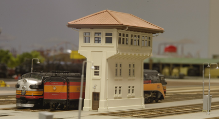
Modeling SP Signal Tower
AL&W Lines - (Santa Clara Type Tower)
AL&W Lines is a manufacturer of fine quality laser cut wood kits. The kit is based on Espee plans for a Common Standard Interlocking Tower. There will be two versions of the tower: one with the stairs ascending from right to left (when looking at the rear of the structure), the other will have a mirror image with stairs ascending from left to right, which is a common arrangement based on photos. alwlines.com
Future plans include a "standard plan" version of the tower (stairs going the opposite direction) and the Burbank Tower.
Bill Decker
Model Tech Studios - (4th St.Type Tower)
The manufacturer is Model Tech Studios. http://mts.inline.net/index.ihtml
http://www.modeltechstudios.com/merchant.ihtml?pid=353&step=4
The Model Tech Studio's mission tower kits model is one in San Francisco. It is a nice kit - nine pages of instructions, fine resin castings, laser-cut windows and beam ends. It's equal or better than a SS Ltd. '70's era plaster kit (though not quite as finely detailed as, say, an AMB SP station kit), represents a model and material that haven't appeared in kits very often, and is a nice size for a model railroad.
For someone wanting a quickie stand-in model, not taking the time to scratchbuild their own, the Model Tech Studios Mission Style Tower kit may do.
Rob Sarberenyi
Old Revell signal tower model
An old HO scale Revell model kit of a signal tower resembles a CS design for a SP signal tower. The windows aren't quite right and other minor liberties were taken in the model design, but otherwise it has similarities to drawings found in Bruce Petty's volumes. At various times over the past 25-years the kit has been released by Con-Cor as a set along with a few other structures. Not exactly 100% Espee, but it does have some of the basic "flavor". pstonecastle@sbcglobal.net
The model seems appropriate for the 1949 time era. If anyone is interested in making models of the buildings, I can get the parts laser cut for you since I now have the design on disc.
Paul (spsmoke)
Suydam
The interlocking tower model is spot on for the yard tower which was in Watsonville and (I think) the Newhall Yard.
Chuck Catania
Mechanical Interlocking System
Pipe Carriers
Interlocking towers controlled the derails, signals and switches with a mechanical interlocking system. A lever in the tower moved a pipe in the field to activate a device. The most notable of these systems is Saxby & Farmer. The pipe line is set at tie height. A home was dug a hole to achieve the right height. The pipe carrier was placed in position and “mechanical interlocking frames put in place.
In the Fresno area, Calwa, Sunmaid, Fresno, Kismit, Hanford and others used this system.
Reference
If one refers to a Santa Fe book "Valley Division Vignettes", pages 180 through 189 show a number of interlocking towers and the mechanical linkage. Most of these towers involve ATSF and SP crossings.
John Houlihan
Modeling Mechanical Interlocking System
Interlocking Pipe Carriers HO scale
Irish Tracklayer
The plastic pipe carriers come in 2 or 4 slot types. Just dig a hole or cut down the foundation to achieve the right height. Glue the pipe carrier on the layout. Put scale pipes in the carrier an the pipe line is set at tie height.
John Houlihan
Reference
There are two photos of the 2 and 4 way pipe carriers in HO. The pictures are under "Mechanical Interlocking" in the SP site.
John Houlihan
http://groups.yahoo.com/group/Espee/photos/album/815161463/pic/740390082/view
http://groups.yahoo.com/group/Espee/photos/album/815161463/pic/1843098880/view
Modeling Interlocking Frames
Scratchbuilding
Many years ago in Model Railroader magazine was an article about constructing a working Interlocking Frames. Gordon Odegard did the original three-part series back in January-March, 1961. Odegard's original brass tappet and locking bar machine is shown in two of the chapters and Chapter 6 shows you how to build the same thing using styrene (much easier/cheaper to work with, believe me). The entire Kalmbach book is only 88 pages in length, with 16 of those pages devoted to the theory, design and construction of a simple mechanical interlocking plant) Jeff Wilson does a good job of explaining the basic theory of interlocking design.
The most difficult part of designing/building a mechanical interlocking, is developing the so-called "dog chart". A mechanical interlocking plant is really nothing more than an analog computer in mechanical form and the necessary Dog charts quickly become rather complicated for anything other than a simple junction or crossing. To find out how the wizards did it back in the heyday of mechanical interlocking during the late 19th to mid 20th Century and the "why" behind the "how", then go on-line to http://www.archive.org/details/railwaysignaling00latirich
Download the classic text "Railway Signaling in Theory and Practice" and carefully read: Chapter XVI "Locking and Dog Sheets". It contains an absolutely outstanding explanation of the theory and practice of designing locking/dog sheets for a railway junction (or drawbridge, gauntlet track, crossing, etc.) -- in short, everything that you could possibly want to know about signaling, derail locks, facing-point locks, etc. -- wonderful reading.
Eric Berman
Reference
Article about constructing a working Interlocking Frames. Model Railroader January-March, 1961, by Gordon Odegard.
You can also purchase a copy of Kalmbach's recent (2006) book: "The Model Railroader's Guide to Junctions", by Jeff Wilson.
Specific Signal Towers
Burbank Junction Tower
References
Tower - Burbank Junction Prototype Modeler Nov/Dec 1987
College Park Tower (San Jose)
College Park Tower was a somewhat larger version of Santa Clara Tower. College Park was located south of Santa Clara, a bit north of the Lenzen Ave. Roundhouse in San Jose. They are somewhat longer version CS towers.
Dayton Ave. Tower (Taylor Yard)
Paint
1930's
The original plans from 1930 called for "exterior surface of concrete and gutter painted 3 coats of lead & oil paint with steel sash and woodwork painted bottle green". Early published black & white photo's from the 30's and 40's clearly show the window trim painted a dark color which is assumed is the green specified on the original plans.
Art Pigott
1950's
See p. 305 in SP freight cars Vol. 3 for a 1950s view. The trim is dark, maybe green, but in the distance, so hard to be sure.
Tony Thompson
1960's
The tower as unpainted concrete with white trim (with the added-on steel steps on the north side).
Art Pigott
1970’s
Photographs from the 70's and later clearly show the trim color to be white.
Reference
Including Dayton Ave. tower at Taylor Yard, along with those found in the SF Bay Area in an article by R. David Read titled "Throwing Levers for the Espee, A Towerman's Memories of Bay Area Interlockers".
Modeling Dayton Ave. Tower (Taylor Yard)
Bob Smaus's wrote about the Dayton tower in RMC. His model is a later version after the stairs on the side were added sometime in the 60's or 70's.
Art Pigott
Golden Gate Tower
Built by the Santa Fe, the original Golden Gate Tower opened on July 1, 1904. It sat elevated over one track of SP's double-tracked Berkeley line. A new second Golden Gate Tower tower was placed in service September 11, 1915. The interlocker was deactivated in 1947.
John Sweetser
Reference
Pg. 227 of the Santa Fe depot book "Coast Lines Depots, Valley Division" has a 1940 photo of Golden Gate Tower.
Hobart Tower
Hobart Tower is at the west end of BNSF's (nee AT&SF) Hobart Yard on the east side of Los Angeles near the City of Commerce. It protected the crossing of the Santa Fe main line and the UP line to East San Pedro. Transfer cuts from both SP at Taylor Yard and PE at Butte Street Yard were delivered to Hobart through this junction. A mile or so to the west is where the Alameda Corridor (occupying the right-of-way of the old SP San Pedro Branch) actually takes separate form.
Rob Sarberenyi
Reference
Menlo Tower
There’s a photo in the Files section showing Jim Scott's F-3 class 2-10-2 #3667 passing the tower. The tower was named "Menlo" in honor of our club's location in Menlo Park, along Espee's Peninsula commute line.
Niles Tower
1973 timetable says the Mococo-Niles junction was a power switch controlled by a switchman, while the three signals there were controlled by the Tracy operator. It was listed under Rule 605 with the other interlockings.
References
Tower - Niles Prototype Modeler Nov/Dec 1987
A good photo of Niles Tower appears on page 113 in Steve's book "Western Pacific Depots and Stations".
Redwood Tower
There was a similar tower up the line a few miles at Redwood Junction. Redwood Tower governed train movements diverging off the Peninsula line traveling over the Dumbarton bridge to Newark and points east.
Santa Clara Tower
A similar tower was located at Santa Clara. This tower has been restored and preserved by the South Bay Historical Railroad Society. This safety sentinel controlled the diverging Coast Line route to Oakland as it split from the historic main line up the Peninsula to San Francisco.Note how the windows differ considerably from the kit, not to mention other trim.
The stairs are ascending from right to left. http://www.sbhrs.org/Buildings/tower/tower.html
Lettering & Numbering
There was a single Santa Clara Tower sign for the track side.
Modeling Santa Clara Tower
AL&W Lines - (Santa Clara Tower)
The first release is patterned after Santa Clara Tower with stairs ascending from right to left. The Santa Clara Tower (HO Scale, kit SP18, $75 plus $5 shipping). The AL&W Lines kit features laser-cut thin plywood parts intended for both peel and stick and glued construction. Windows are finely cut--an important feature for a structure with windows completely spanning three of four upper story sides. Basic detail is provided for the upper story interior including the interlocking case, operator table with typewriter drop table, wall-mounted model board and a clock case. Decals are provided for the model board, clock face, a calendar and the single Santa Clara Tower sign for the track side. Additional sign board blanks are provided on the plywood stratus.
Because the windows on these tower kits are large, it's only natural for an interior be installed. Bruce is working on an interior kit, complete with lever box! This will really help bring the tower kit alive on your layout! Just remember to install prototypically correct dim lighting. alwlines.com
4th Street Tower
Below the third floor in photos of the prototype there’s 10 eaves. 4th St. Tower never featured a signal mast on the roof.
References
Tower - 4th St. NMRA Bulletin Apr 1983
Drawings
Plans and a few photos of SP's 4th Street Tower appear in "Southern Pacific Lines Common Standard Plans, Volume 4", by Bruce Petty.
Rob Sarberenyi
Modeling 4th Street Tower
Model Tech Studios
The Model Tech Studio's mission tower kits model is one in San Francisco. It is a nice kit - nine pages of instructions, fine resin castings, laser-cut windows and beam ends.
There's minor warping on some of the side pieces - maybe 1/16", and the parts are flexible enough to be pressed flat with light pressure. It should be easy to fix the warp during assembly. The hipped tiled roof is cast as one solid piece, and has one corner raised about 1/32" because of warping - not perfect, but it shouldn't affect the look of the model too much. The castings are all thick - on the order of 1/8", much thicker than a Westerfield freight car kit. The castings have a decent sand finish and minor raised detail for the foundation and projections - they're not elaborately detailed, but the lack of cracks and detail is appropriate for a new concrete building.
When comparing Model Tech Studios' HO scale "Mission Style Signal Tower" to Espee's tower which once stood at 4th Street, you can spot some of the differences. The windows need to be changed. Count 9 (eaves?) below the third floor while in photos of the prototype there’s 10. Window placement on the lower floors differ (second level windows appear too low), not to mention the 4th St. Tower never featured a signal mast on the roof as depicted in the kit, although this can probably be left off.
The tower windows are somewhat modernized in these view vs. how the tower was constructed
The material used to make the tile roof is Plastruct Spanish Tile roofing, it's the 1:100 scale size. The windows are all Grandt Line, cut and glued to match the spaces. There is even a tiny Model Board inside the Tower on the top floor, but the lights don't move when the trains do.
Photo of the raw castings are here: http://gallery.me.com/rbowdidge/100077
http://cgi.ebay.com/ws/eBayISAPI.dll?ViewItem&item=190445057694
Find the mission style tower kit available for a lower price (than eBay) here:
Pete scratchbuilt model http://tinyurl.com/2ccpuxd
Raised letters for "4th Street Tower"
Get a plastic lettering set from an arts & crafts store. The letters are about 1/4" tall. They're all on a plastic sprue -- just nip them off and glue in place. they are Plastruct styrene letters that come in various sizes.
Tim O'Connor